Sunday 30 October 2011

Materials


Here is a list of materials that can be extracted from the pictures I took of the Guildhall


Wooden beams in the attic. Beams are not straight and look worn over time. The attic was found above the larger room on the second floor.


Brick fireplace. Bricks look worn down. Walls are painted white but are not clean due to the building work that has been going on.


Another fireplace. Similar brick surroundings. Fireplace has a metal grill. The trough area in front contains tiles with a wooden bridge around them.


The walls are blended in with the wooden beams that support the building. The ceilings are painted white.


This room shows some of the modernised features of the guildhall with the wooden board and plug sockets. The rest of the room has a brick wall on the left an a plaster painted wall on the right. The ceiling here is wooden beams.


This picture shows the floor of the larger room upstairs. The floor here was wooden floorboards. In this room they were all bent and out of shape. This will be corrected in the redevelopment.


This is the back end of the conference room, showing a potential new window that will be fitted. The walls in this room are different to the rest of the building. They are painted the same colour but have bigger sections.


This is the other end of the conference room. This picture shows the wooden beams that run across the room. It also shows the wooden benches that are there (two of them).


This picture shows the window. This is fairly worn and will be replaced in the redevelopment. The frames are metal.

Finchingfield photos


Here is a link to the photos that I took on the Finchinfield trip.


I will go through them and assess the different materials. This will be useful later on once the modelling has been completed as we won't have to spend loads of time researching materials then.

Friday 21 October 2011

UVW Mapping

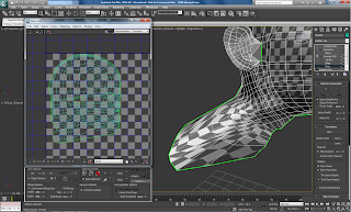
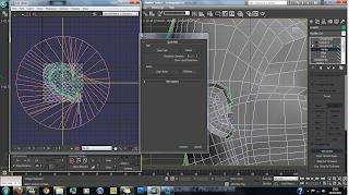
The next stage of the model is to create the area that the skin will go on. To do this we use a modifier called Unwrap UVW. This is placed on top of the editable poly modifier. This allows us to arrange the vertices in such a way that we will be able to create our own skin material. In this case, I will be pasting my face from the original photograph onto this mesh. To start with, select the unwrap uvw modifier from the modifier window. Next select the entire head in the faces sub-menu. Select all of the polys using the spray tool. I did not select the ear at all, this is very important. The ear will be mapped separately. Next I need to use the gizzmo, cylindrical in this case. I lined this up over my head in the top view and also used the front view to do so.


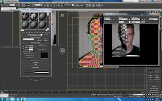
Next, I added a checkered material to the model, bringing up material editor and finding the checkered material. I increased the checker pattern and applied it to the model. This will enable me to see where the creases are within the model.


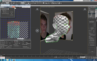
The next step was to click on edit parameters. This is where the work will be done in UVW mapping. This shows where there are errors in the model and they can displayed by choosing select, show inverted faces. It is then possible to adjust these faces until they are correct. It is important that all the quads are pulled out to be as quad like as possible.


The relax tool can be used to push vertices apart. I found it useful at times but it could cause more messy results.


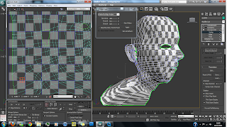
Here is the results of the head modification.


After this was done it was time to concentrate on the ear. To do this, I went back to paint spray mode and selected the polys that I hadn't chosen previously, the ear. This time I didn't use a cylindrical Gizzmo, I used Planar and Pelt. This wrapped around the ear nicely. In pelt mode you can use the pelt and relax functions to change the vertices. When the ear first appears it is way too big, so it needs to be shrunk down. Once the overlapping and inverted faces are removed it is time to move onto the next stage of the process.


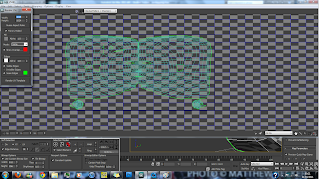
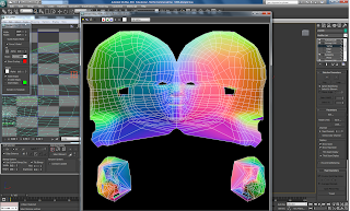
Going back into edit mode we see the results of the modifications that I've made. I move the ear down low into the bottom left hand corner as the ear will be textured separately. Now it is time to add another unwrap UVW modifier this time on top of symmetry. Now both sides of the head will appear in edit mode. Selecting the head and making sure the right hand side is now selected, mirror the image and pull it across to the right hand side. Doing the same with the ear we are left with the below image.


Next, the vertices along the seam need to be welded together. This can be done easily by highlighting the two vertices and pressing control w.


After rendering the UV map in normal mode we are left with the below image. I will now be able to save the image and start texturing in photoshop.

Welding the Ear

One thing that I had missed out when modelling the ear was welding it to the head. I had done this because it was a bit tricky and thought would be better to do later on. I had to do it before UVW mapping, so the time was now.


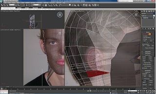
It was a tricky process. Firstly I had to create more polys at the back of the ear using the create tool. This was hard because you have to create the polys that link up with the vertices already on the head. After some frustration and perseverance I was successful in matching up the vertices. Welding them together using control W, my ear was finally complete!

Removing the artifact


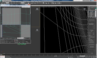
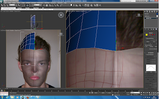
I removed the artifact running down the middle of the model when the symmetry is added. I did this by moving the vertices further right in the left view. This creates a smoother surface at the edge, so that there are no points edges.


By doing this, we flatten the face and make the model look far better.

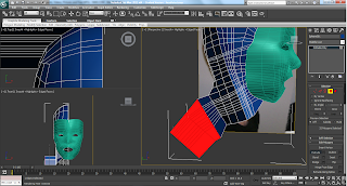
I have also remodelled the neck and shoulders. They are not a crucial part of the model but they are still needed and without them it would look a bit odd!

Nose

The next step is to correct to nose and create the nostrils. It is important I have a number of vertices surrounding the nose as the tip of the nose needs to stand out.

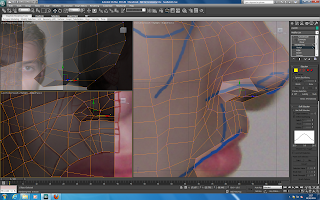
The first thing to do was to create some extra lines around the nose. This was done using the cut tool. Another trick for doing this was selecting the inside lines and holding shift and dragging them out. These is done where I deliberately left space for the nostrils when modelling the face.


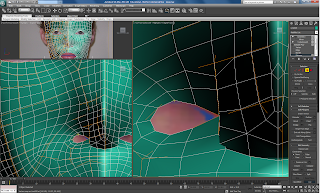
After welding these points together, it is important that you look at the nose in perspective view and try to get the nostril in position. Once this is done, use attach to create another poly in the gap.


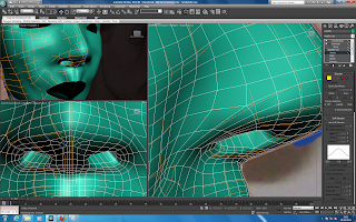
After this is done, the new polygon can be extruded upwards. This creates a nice hold for the nostril. Using the perspective view again to check that it is positioned correctly, we have our nose!


The final thing to do is give a better shape to the nose. This is done in left view by dragging the vertices towards the tip of the nose to make it more rounded/less rounded depending on what needs to be done. Here is my final nose!


After this, we can use a similar method to do the lips. By pulling out the lines at the top and bottom of the lip (press alt x to make the model see through) we can position them to where they are on the image. It is vital that there are two sections to the lips. Once these have been positioned, the first line can be moved to add specific curving that is needed.


Wednesday 19 October 2011

Ear

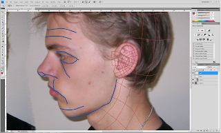
Next it is time to create the ear. First things first I had to draw the topology lines on the original picture. Again making sure I had no triangles. The topology lines have some loops, but I changed this when modelling.


To start creating the ear I used the same method as creating the face. Using the line tool and snaps toggle, I traced over the topology lines. before converting one quad to a poly and attaching the rest.


Next I used the front view to pull out the ear to give it the correct depth. I encountered a slight problem here, there ear on my front picture is shorter than the ear in my left picture, which is bizzare as I matched the pictures up perfectly in photoshop at the start. This will have to be worked around, I will just change the size of it at the end until it looks right.


Next it was time to pull out some of the features. I used the inset tool to push through the surface of the ear. This gives the edge of the ear a platform.


The next step was to use the chamfer tool to smoothen off the edges around the raised section. To do this I selected all of the polys around the edge before choosing Chamfer.


Te last step for the ear was to create the back of it and attach it to the head. To do this, using the line selection option, shift and the scale tool, the back of the ear could be pulled out.


To attach the ear to the head, I created a small flap. This was then rotated and put into place. The ear was then set into place using the attach tool, and then the vertices welded in.

Creating the rest of the head

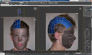
The next task was to create the head and attach it to the face. Firstly I needed to draw extra topology lines onto the original photo. This will act as a guide for the polys when they are created. I have also drawn topology lines onto the ear, but will come to this in a later post when I construct the ear itself.


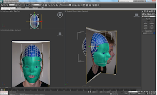
Moving into 3ds max, a sphere is used as the basic shape. After shaping it so it is the correct width and rough length, it is time to start changing the vertices so it becomes head shaped. I also shrunk the number of sides to 24 as it will be awkward to work with too many. After this is done, it is time to convert the shape to an editable poly.


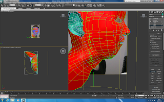
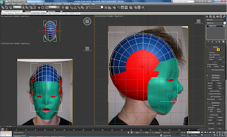
Using the spray selection tool, I was able to select a range of polys at once and delete them. In this case I removed most of the sphere (see red section). I will then be able to extend the polys to create the rest of the head. It is also important to select and delete the right hand side of the sphere and delete it, as the symmetry modifier will add the right hand side.


Next, it is time to remove some of the polys.To do this there are a couple of useful tools, rather than selecting every individual one and pressing backspace. After selecting every other line (see pic below) I pressed ring and the adjacent lines were all selected too.


After this, hitting the collapse button removes the selected lines and gives an easier platform for modelling.


Using the snaps toggle, soft selection and weld, it is possible to connect the vertices to the face. It is a simple case of dragging them into position and then welding.


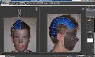
After reshaping some of the vertices it was time to extend the polys down to create the rest of the head. TO do this I selected the lines I wished to extend. Holding shift, it is possible to create new polys very easily just by dragging. Another useful tool is the create tool and the cut tool. The create tool enables you to create new polys by connecting the four vertices together. The cut tool enables you to add new vertices wherever you want. It was a tough procedure I found creating the head, trying to have no triangles or five sided shapes resulted in the being a lot of vertices. Hopefully this won't cause too many problems, but it will mean I need to take care later on when changing little parts of the face.


After extending the polys down in the left view I was able to extrude out the shoulder. This had to be done in perspective view, where as everything else so far has been done in the left view.


Here is the result. It's ok for the moment, I will spend time tweaking things later on.


Tuesday 11 October 2011

Symmetry & Turbosmooth

The next step was to create the other side of the face, as well as rounding off some of the sharp edges. To do this the following modifiers are used.

Symmetry. When using the symmetry modifier it is easy to replicate the face exactly how I want it. After expanding the modifier select mirror and ensure it is reflecting along the X axis. Flip also needs to be checked otherwise the face will be the wrong way round. When mirror is selected, you are able to drag the other side of the face into the desired position. This can create 'artefacts' when rendering... in other words a bump where the two mirror areas have connected. It just so happens that I have one single artefact running the whole way down the face!


Turbosmooth. I used this a lot last year and it is very useful. By turning up the iterations in turbosmooth, more edges are added when you render. This makes all the shapes curve off nicely. It also shows you where there are problems with the vertices which means you can go and correct them.


Remaking the Mask

I decided my last mask wasn't good enough so I remade it. After realising I should have saved a previous version of the file with just the lines (D'oh!) I set about retracing them with the line tool. Luckily I've had some practise at this now so it didn't take very long!

After the necessary removing of triangles and 5 sided polys, I set about welding the lines together and bringing them out on the left view. Taking a lot more care this time I was able to produce a better mask. Goes to show practise... or being less careless does the trick!

I'm not entirely happy with it, but I can come back to change little bits nearer the end if I have time. A plus point is that I now have two versions of the mask at the same stage, with slightly different poly shapes on each one. This could come in useful if things get tricky later on. For now it is time to crack on and build a head!


I did have to delete a poly when modelling as I discovered another 5 sided shape. I managed to find a way to get around it by putting in another edge that runs from the forehead down. This area is connected to a fiddly part of the face, but they are all 4 sided! By using the weld tool along with swift loop, I was able to delete the 5 sided shape and put in two rectangles.

Making a Mask

I found it incredibly fiddly pulling out the lines. There were too many topology lines which made it quite a confusing process. If I could go back to the start I would use less topology lines.


I took each vertex and matched it to where it should be on the side of the face. In quite a few cases this led to overlapping lines which caused a rip or tear in the structure. After dragging out the vertices there are many small areas that I need to adjust to make the face more smooth and realistic.


As you can see in this rendered image there are lots of creases and errors. My next step is to fix this.


Once I have sorted this problem out, I will be able to add the symmetry modifier. Using this does mean that I will end up modelling a 'perfect' face as the features on the left will be copied onto the right. I think my face is fairly symmetrical anyway so hopefully it will still look like me!